Frequently Asked Questions (FAQs)
RollBy™ OnBoard Speedometer FAQs
1. Are Rotation Wheelsets available for other scales and track gauges?
Boulder Creek Engineering does not stock other Rotation Wheelsets at this time. Please contact us if you would like a scale or gauge that we do not offer — we may be able to build a custom wheelset for you.
2. What does the green LED flash indicate?
The LED flash shows that the RollBy™ OnBoard Speedometer is active.
The OnBoard Speedometer "sleeps" after 10 seconds of inactivity to conserve battery life. When movement is detected, or the battery is reconnected, the OnBoard Speedometer LED flashes and the BLE radio "wakes up" and begins transmitting data.
3. My App showed speed for a short time but then stopped working. What could be wrong?
The Rotation Wheelset magnet is very powerful and will accumulate magnetic debris. It's great at finding lost screws! Check to see if debris is jamming the axle and preventing it from turning.
Clean your Rotation Wheelset magnet periodically with sticky tape as shown in the product video. You may need to clean the magnet every few feet the first couple of laps around your layout!
4. My Rotation Wheelset spins freely on the workbench but my railcar jerks and bucks when rolling along my track. What could be wrong?
Track nails will grab the wheelset magnet, causing the car to buck and swinging the speed display faster and slower. Removing or driving the nails deeper will reduce or eliminate the problem.
HotShot™ Trackside Speedometer FAQs
1. What are the power requirements for the HotShot™ Speedometer?
The HotShot™ Speedometer requires 7 to 9 Volts AC or 9 to 12 Volts DC, and will draw up to 100 mA with the included Photo Sensors.
HotShot™ Speedometer will draw up to 150 mA with NightScope™ Infrared Detectors.
You will need to provide a power source of the correct type (AC or DC) and voltage, with at least the current capacity above. For example, the Radio Shack Universal AC Adapter (#273-1121) works well. Simply clip off the modular connector plug and separate and strip the wires. You will need to adjust it to 9 VDC before connecting it.
Warning: Do not exceed 9 Volts AC or 12 Volts DC as this will damage the Speedometer circuit board.
2. I installed my HotShot™ Speedometer with the included Photo Sensors. The Speedometer occasionally triggers when someone walks by. How do I prevent this?
Passers-by may be casting a shadow on your layout. To avoid this problem, Auto-Adjust your Speedometer&';s Light Level setting as described in Section 4 of the Product Manual.
When the Speedometer displays "oPn", be sure to have someone cast a shadow as is typical for your layout before pressing the pushbutton to go on to the next step. This will resolve a problem with passing shadows.
3. When Auto-Adjusting my HotShot™ Speedometer for Photo Sensors, I receive the error "E 0". What can I do?
An "E 0" error is displayed when HotShot™ Speedometer&';s Photo Sensors are not receiving enough light when uncovered. One solution is to increase lighting in that area or to move the Photo Sensors to an area on your layout with more light.
A second solution is to purchase two NightScope™ Infrared Detectors for use in place of the Photo Sensors. Infrared Detectors will work even in complete darkness.
4. What can I do if I receive the error "E 1" (lighting too bright) when adjusting for Photo Sensors?
First, be sure that you cover both Photo Sensors before pressing the pushbutton when "cAr" is displayed during Auto-Adjustment. This can cause the "E1" result if you do not.
One solution is to slightly dim the lighting in the area or move the Photo Sensors to an area that has slightly less light. One option for dimming the light is with scenery such as trees, bushes or the like.
A second solution is to press the Photo Sensors slightly deeper into their holes in the roadbed. As little as 1/8" may be sufficient.
5. What can I do if I receive the error "E 2" (lighting contrast too small) when adjusting for Photo Sensors?
First, be sure that you cover both Photo Sensors before pressing the pushbutton when "cAr" is displayed during Auto-Adjustment. This can cause the "E2" result if you do not.
This error may show up for rail cars that do not completely block the light, such as log buggies, or even tank cars. Try Auto-Adjusting with box cars.
If you have this problem with box cars, you most likely have lighting that is almost too dim or bright. Increase or decrease your lighting in the area as discussed in the FAQs above.
BrassHat™ Sound Recorder FAQs
1. What are the power requirements for the BrassHat™ Sound Recorder? For the BrassHat™ Announcer?
Both the BrassHat™ Sound Recorder and BrassHat™ Announcer require 7 to 9 Volts AC or 9 to 12 Volts DC, and will draw up to 150 mA.
You will need to provide a power source of the correct type (AC or DC) and voltage, with at least the current capacity above. For example, the Radio Shack Universal AC Adapter (#273-1121) works well. Simply clip off the modular connector plug and separate and strip the wires. You will need to adjust it to 9 VDC before connecting it.
Warning: Do not exceed 9 Volts AC or 12 Volts DC as this will damage the Sound Recorder circuit board.
Warning: Do not share an AC Adaptor with other electronics as this will lead to humming or buzzing interference in the audio output.
2. What speakers do you recommend for the BrassHat™ Sound Recorder and Announcer?
While you can connect any 8 ohm speaker to the SPEAKER output of the Sound Recorder or Announcer, we recommend a set of powered speakers with a 1/8" (3.5 mm) input plug connected to the Sound Recorder/Announcer&';s LINE OUT jack.
Powered speakers have enclosures designed for their amplifier and speaker characteristics. They produce a higher sound quality with volume control. Some include tone control too.
We have had good results with low priced powered speakers from Amazon priced at about $10. The CA-2014 Computer Speaker System from Cyber Acoustics is a good choice.
Warning: Connecting a speaker rated less than 8 ohms to the SPEAKER terminal block will damage the circuit board.
TrainBoss™ Defect Detector FAQs
1. What are the power requirements for the TrainBoss™ Defect Detector?
The TrainBoss™ Defect Detector requires 7 to 9 Volts AC or 9 to 12 Volts DC, and will draw up to 250 mA.
You will need to provide a power source of the correct type (AC or DC) and voltage, with at least the current capacity above. For example, the Radio Shack Universal AC Adapter (#273-1121) works well. Simply clip off the modular connector plug and separate and strip the wires. You will need to adjust it to 9 VDC before connecting it.
Warning: Do not exceed 9 Volts AC or 12 Volts DC as this will damage the Defect Detector circuit board.
Warning: Do not share an AC Adaptor with other electronics as this will lead to humming or buzzing interference in the audio output.
2. What speakers do you recommend for the TrainBoss™ Defect Detector?
While you can connect any 8 ohm speaker to the SPEAKER output of the Defect Detector, we recommend a set of powered speakers with a 1/8" (3.5 mm) input plug connected to the Defect Detector's LINE output.
Powered speakers have enclosures designed for their amplifier and speaker characteristics. They produce a higher sound quality with volume control. Some include tone control too.
We have had good results with low priced powered speakers from Dell and Amazon priced at about $10. The CA-2014 Computer Speaker System from Cyber Acoustics is a good choice.
Warning: Connecting a speaker rated less than 8 ohms to the SPEAKER terminal block will damage the circuit board.
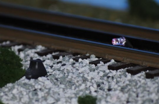
3. I'm a large scale modeler and use Code 332 rail. Will the TrainBoss™ Defect Detector work for me?
Yes, but you will need special Axle Sensors to clear your taller rail.
If your rail is larger than Code 125 (1/8"), please let us know when you order (send us an email). We will provide longer LED leads on your Axle Sensors.
Longer LED leads will allow you to install the Axle Sensors across one rail (as in Figure 1 in the Product Manual) with the LED inside the rail and a bit higher than the railhead. When you bend the LED back to face the sensor, it will be pointing down slightly but the infrared beam will clear the railhead and hit the sensor.
Drew Madere is an outstanding O Scale 3-Rail modeler. This photo shows how he installed his Axle Sensors. See his February 20, 2011 photos on his website for more views.
4. My TrainBoss™ Defect Detector miscounts axles. How do I correct that?
Incorrect axle counts are caused by either poor Axle Sensor alignment or low-hanging details on cars -- or both. By correcting these two error causes, your TrainBoss™ axle counts will be right on the money every time.
Installing TrainBoss™ Axle Sensors shows how to adjust your Axle Sensors for optimal performance. Follow these suggestions and test with long trains and a variety of equipment.
The same article also explains how to find low-hanging details on cars (see "If you find an occasional high axle count" at the end). Removing the offending interference will eliminate the incorrect axle count. Coupler "glad hands" will not trigger the Axle Sensors.
Finally, some model railroad electronics installed on railcar trucks hang low enough to interrupt the Axle Sensor infrared beam and cause a miscount. The EOT Device from Ring Engineering, for example, may cause one axle to be counted for the two axles in the last truck of a train.
5. After installing my TrainBoss™ Defect Detector, the yellow LED above the "S" input doesn't flash when a car goes by, and I don't hear a speed or length message. Is there something wrong with the "S" Axle Sensor?
Check to see that the "J9" jumper was removed as described in Step 2 of the Wiring Instructions (Section 4) in the Product Manual. This jumper must be removed to allow the "S" Axle Sensor to operate and for the Defect Detector to produce Speed and Length reports.
6. After installing my TrainBoss™ Defect Detector, every train reports a defect. Is there something wrong with my Detector?
Check to see that a normally open (n. o.) type push button is connected as the Next Train Switch as described in Step 6 of the Wiring Instructions (Section 4) in the Product Manual. A normally closed (n. c.) type will cause the problem you describe.
WeighStation™ Track Scale FAQs
1. What are the power requirements for the WeighStation™ Track Scale?
The power requirements for the WeighStation™ Track Scale are as follows:
The Digital Display (WS-22, WS-21D) Track Scale requires 7 to 9 Volts AC or 9 to 12 Volts DC, and will draw up to 250 mA.
The Meter Display (WS-21M) Track Scale requires 7 to 9 Volts AC or 9 to 12 Volts DC, and will draw up to 50 mA.
You will need to provide a power source of the correct type (AC or DC) and voltage, with at least the current capacity above. For example, the Radio Shack Universal AC Adapter (#273-1121) works well. Simply clip off the modular connector plug and separate and strip the wires. You will need to adjust it to 9 VDC before connecting it.
Warning: Do not exceed 9 Volts AC or 12 Volts DC as this will damage the Track Scale circuit board.
2. Does the WeighStation™ Track Scale really weigh model railroad railcars?
No. This product simulates weighing for model railroad operations, and does not provide the true weight of rail cars.
3. Does the WeighStation™ Track Scale have a digital output connection (USB, RS232, etc.) for printing waybills?
Yes. WeighStation™ Track Scale Model No. WS-22 introduces the Report Data Link, transmitting range and weight messages at 2400 bps with ASCII characters. The Data Link can be connected to point-of-sale printers, C/MRI, computers, and other electronics. See the WeighStation™ Track Scale Data Link Guide for details.
In support of pencil and paper, our website has ideas for adding weight to traditional 4-cycle car cards.
4. When weighing a string of freight cars, my WeighStation™ Track Scale will not ramp down to zero between cars. What do I need to do?
The NightScope™ Infrared Detector should catch the space between cars and trigger the WeighStation™ Track Scale for each car. The Infrared Detector is fairly powerful, as it has to work at awkward angles in very short spaces, especially in N Scale. We have seen it detect couplers between cars, and that may be what you are experiencing.
If mounted between the rails, try moving your Infrared Detector off center to avoid the couplers. Better yet, move it outside of the rails for even a non-gantlet installation.
If your Infrared Detector is already mounted outside of the rails (at the distance shown for a gantlet arrangement in the Product Manual), be sure the Detector is mounted so the LED and Sensor Shroud are below the roadbed surface. Pull the Detector down a bit further to see if that catches the space between cars. You can also try rotating the Detector in it's hole so the LED and Sensor are at a right angle to the rail. As the LED moves away from the rails, the sensitivity of the Detector will drop.
NightScope™ Infrared Detector FAQs
1. What is the difference between the NS-340/342 and NS-350/352 NightScope™ Infrared Detectors?
The NS-340/342 Detectors included a weak (4.7k ohm) pull up resistor on the Detect Low (YELLOW) output. This resistor is removed in the NS-350/352 Detector, allowing it to interface with a greater variety of model railroad electronic systems.